.svg)


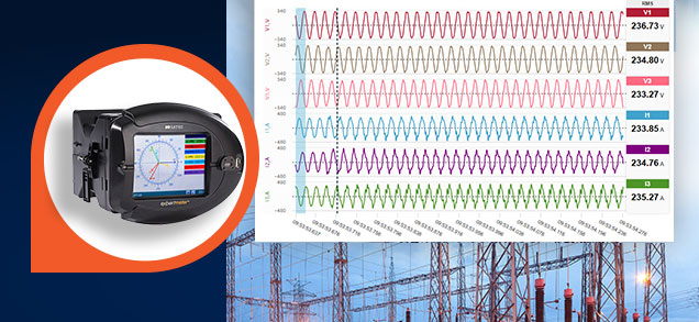
Class A (Ed. 3) Power Quality Analyzer

The PM180 Power Quality Analyzer is a high performance power analyzer with extensive track record
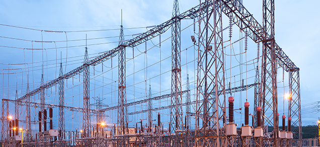
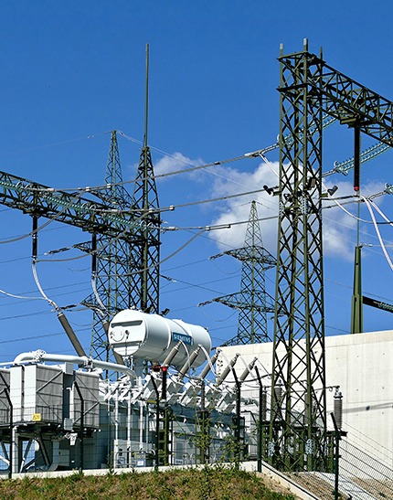
serving as the hardware platform for power quality monitoring systems in national grids around the world
and is certified by the NMI institute as a Class A, Edition 3, analyzer, per IEC 61000-4-30.
Class A (Ed. 3) Certification
PQ Reports and Statistics
Extensive Parameter Recording
Fast Transient Detection
*using the transient module
Available options:
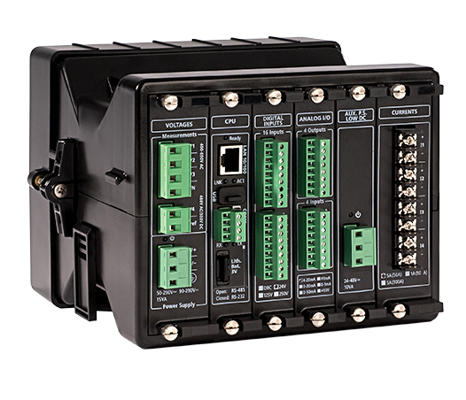
Operating range:
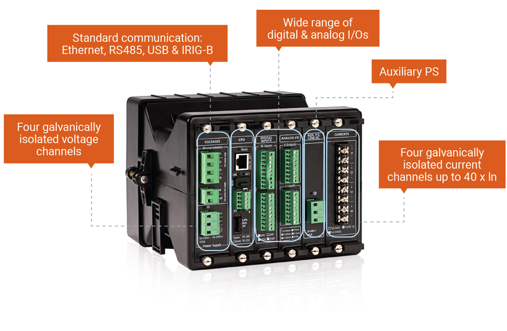
Wide range application up to 828V AC
5th AC/DC voltage input:
monitoring substation battery (up to 300V DC)
16 Digital Inputs
available options:
8 Relay Outputs
Electromechanical (SPST Form A)
available options:
Combo: 8 Digital Inputs + 4 Relay Outputs
Available as:
Built-in:
Optional/additional: (1 per device):
Built-in: 85-265V AC / 88-290V DC
Additional options:
Complies with EN50022
 PM180 Datasheet
PM180 Brochure
HACS Datasheet
PM180 Brochure - RUS
PM180 Datasheet - FRA
Phasor Measurement Unit PMU
PM180 Installation Manual
PM180 Operation Manual
PM180 Passport - RUS
PM180 Installation Manual - RUS
PM180 Operation Manual - RUS
PM180 PLC Configurator
Bay Control Unit
Disturbance Direction Detection
EN50160-2010 PQ Recorder
Fault Locator
PMU App. Note
PM180 DNP
PM180 IEC 60870-5
PM180 IEC 61850
PM180 IEEE C37.118.2
PM180 Modbus
PM180 Datasheet
PM180 Brochure
HACS Datasheet
PM180 Brochure - RUS
PM180 Datasheet - FRA
Phasor Measurement Unit PMU
PM180 Installation Manual
PM180 Operation Manual
PM180 Passport - RUS
PM180 Installation Manual - RUS
PM180 Operation Manual - RUS
PM180 PLC Configurator
Bay Control Unit
Disturbance Direction Detection
EN50160-2010 PQ Recorder
Fault Locator
PMU App. Note
PM180 DNP
PM180 IEC 60870-5
PM180 IEC 61850
PM180 IEEE C37.118.2
PM180 Modbus
Transient Recorder Module
Records voltage transients of up to 2kV (L-G) at 1024 samples/cycle per channel
Fault Recorder Module
Additional current input offers separated metering & protection CT connection, records current faults of up to 200A (40*In)
PMU Functionality
Phasor measurement unit (PMU) provides synchrophasor and frequency measurements compliant with the IEEE C37.118.1 P performance class, and real-time cyclic exchange of synchronized phasor data with the substation phasor data concentrator (PDC) based on the IEC 61850-9-2 sampled value (SV) service.
Auxiliary Power Supply
(max. one auxiliary power supply per PM180)
Contact now