>  Home >  Products >  BFM-DFR

40-Channel Digital Fault Recorder

Monitoring up to 12 three-phase current channels sharing common voltage or two independent voltage sources.
Designed for substation digitalization in retrofit projects, the Branch Feeder Monitor provides Digital Fault Recording @ 40 X nominal current and full substation digitalization, enabled by extensive I/O options and communication interfaces.
It is a modular device, fitting every application with the optimal amount of current channels, I/Os and communication interfaces.
The BFM II is designed to interface SATEC’s High Accuracy Current Sensors.


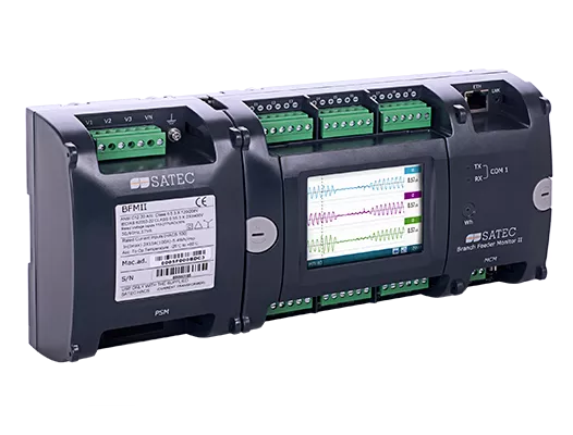
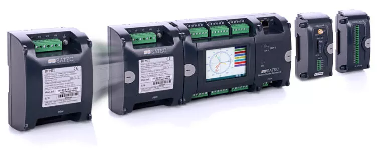
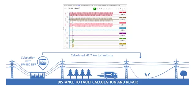
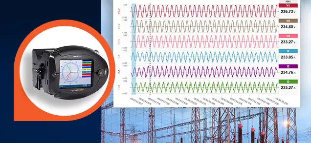
Multi-circuit Digital Fault Recorder: Modular options for fault recording

  • Recording waveforms @ 64 samples/cycle; up to 40 x In
  • up to 12 three-phase loads
  • up to 36 single-phase loads
  • various combinations of the two

Communication

  • Built-in ports: RS485; ETH
  • Optional: 3G modem
  • BACnet; Modbus RTU; DNP3.0
  • IEC 60870-5-101/104

Digital & Analog I/O (modular)

  • Digital: up to 72 digital I/O
  • Analog: up to 4 inputs

Current Inputs

40mA for HACS CTs
recommended: 100A or 200A rated HACS for installation on protection CTs’ 5A secondary

Technical Specifications

Digital Fault Recorder

  • Waveform capture and logging
  • Up to 40 x In
  • sampling rate: 64 samples/cycle
  • simultaneous recording of 12 three-phase current channels
  • Dedicated DFR setup

Power Meter

  • Class 0.5S / 0.5 accuracy per IEC 62053-22 / ANSI C12.20
  • Power: True RMS volts, amps, power, energy, power factor, neutral current and many more
  • Power quality: individual voltage & current harmonic spectrum and harmonic angles up to 25th order harmonic
  • Voltage and current THD, TDD and K-Factor
  • Event and parameter data-logging

Harmonic Analyzer

  • Voltage and current THD, TDD and K-Factor,
  • Voltage and current harmonic spectrum and angles, up to the 25th order harmonic

Modular I/O

  • Up to 72 DI
  • Up to 18 DO
  • 4 Analog input option

(see Module tab for detailed spec)

Programmable Logical Controller

  • Embedded programmable controller
  • 4 control setpoints, programmable thresholds and delays for each submeter
  • Relay output control (for alarm and protection)
  • 1 cycle response and update time

Graphic Display Module (GDM)

Optional 3.5” 320×240 pixel touch-screen graphic display

Real Time Clock

  • Built-in clock and calendar functions
  • Accuracy: < 5 sec/month @ 25°C

Communication interfaces

Built-in:

  • RS485
  • Ethernet 10/100Base-T

Optional:

  • 2G/3G modem

Communication Protocols

  • Modbus
  • ASCII
  • BACnet
  • DNP3.0
  • IEC 60870-5-101/104

Current Inputs

  • 40mA current inputs designated for SATEC’s HACS CTs.
  • Recommended HACS rating: 100A or 200A nominal current, to be installed on the protection CT’s secondary (5A) allowing the reading of up to 40 x In accurately yet without saturation

Voltage & Power Supply

  • Nominal voltage: 120/208 – 277/480V AC (L-N/L-L)
  • Input range: 70-561V AC 50/60 Hz (direct connection, L-L)
  • Self-Energized from measured voltages
  • Optional auxiliary power supply:
    50-290V AC, 40*-290VDC


* Above 60°C – minimum 90V DC

Meter Security

  • 3 levels Password security for protecting meter setups and accumulated data from unauthorized changes
  • Anti-tamper design (wiring seal)

Mounting

  • DIN-rail

The BFM Digital Fault Recorder supports various add-on modules:

  • Current inputs
  • I/O
  • Auxiliary power supply
  • 2G/3G modem

please see below for options and rules regarding possible combinations

Current Input Modules (CIM)

up to 2 CIM modules per instrument
adding up to no more than 36 single-phase current channels altogether

  • 6 current input module – HACS version
  • 18 current input module – HACS version

img

I/O

up to 4 DI modules per BFM
up to 2 RO module per BFM

  • 9DI: nine digital inputs (dry contact / 24/125/250V DC). 1-cycle update time; unlatched, latched, pulse and KYZ operation; energy pulses
  • 18DI: eighteen digital inputs (max. 4 modules per device)
  • 4AI: four analog inputs, selection of: 0-20mA, 4-20mA, 0-1mA and ±1mA output; 1 cycle update time
  • 9RO: nine form-A relays (max. 2 modules per device)

Auxiliary Power Supply

50 – 290V AC, 40*- 290V DC


* Above 60°C – min. 90 VDC

img

2G/3G Cellular Modem

Includes 2nd RS-422/485 communication port

Contact now

one of our experts


    top