From Physical Boundaries to Operational and Business Decisions
A data center is a different kind of electrical facility. This is not necessarily because its equipment is entirely different from that found in industrial or commercial facilities, but because every outage, disturbance, capacity constraint, and measurement point has a different significance.
In a conventional facility, the metering system is used primarily to understand energy consumption, peak demand, costs, and the allocation of consumption. In a data center, it must also show which path supplies the load, how much capacity remains available on each path, what happens when a component is lost, and what is driving changes in efficiency metrics.
A data center metering system is therefore not an add-on to the electrical system; it is part of the facility’s ability to monitor, understand, and investigate its critical infrastructure.
The First Shift: How the Designer Approaches the Problem
The most important difference between designing a metering system for a conventional facility and for a data center is not the number of meters, but the starting point. In a conventional facility, the question is which loads should be measured. In a data center, the first questions are which decision the data must support and under which operating or failure condition.
For example, during a voltage dip, the system should help determine whether the event originated on the utility grid. When a UPS transfers to bypass, synchronized input and output data should be compared. If path A is lost, the effect of the transfer on path B must be visible. The same applies to an increase in PUE: the measurements should help identify whether the change is associated with cooling, losses, auxiliary loads, or a change in IT load.
A data center’s redundancy philosophy illustrates this distinction clearly. When the electrical infrastructure is designed around independent supply paths and systems, such as A/B, N+1, and 2N, the metering layer must preserve the same separation. Reducing the data to a single total may conceal an overload, imbalance, or capacity constraint on one path precisely when the system is required to operate in a redundant mode.
Define the Measurement Boundary Before Selecting the Meter
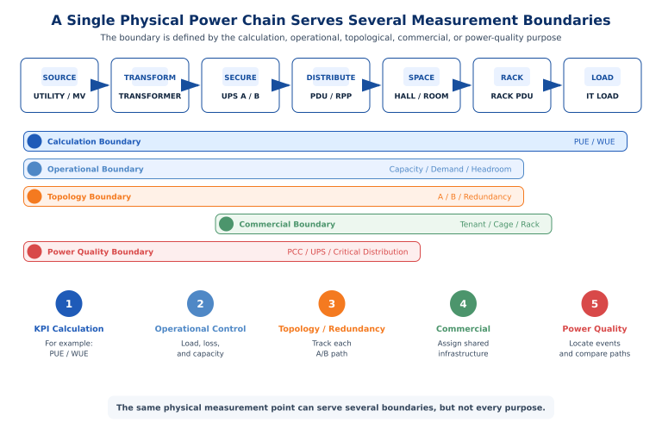
An accurate meter installed at the wrong boundary can provide a completely accurate value and lead to a completely incorrect conclusion. A data center does not have one measurement boundary; it has several partially overlapping boundaries, each serving a different purpose.
- Calculation Boundary – the boundary used to calculate key performance indicators (KPIs), such as PUE or WUE.
- Operational Boundary – the resolution required to identify loading, losses, available capacity, or an exception.
- Topology Boundary – the separation between sources, transformers, UPS systems, A/B paths, switchboards, PDUs, halls, and racks.
- Commercial Boundary – the point separating shared infrastructure from a tenant, cage, suite, or rack.
- Power Quality Boundary – the points at which it is necessary to know not only how much energy or power passed through, but also the quality of the supply and where a disturbance occurred.
The metering architecture should follow the power chain:
Source -> path -> distribution -> room/hall -> rack -> IT load
In parallel, it should also follow the cooling, water, and auxiliary load chains.
The Data Center Type Changes the Metering Approach
Enterprise Data Center
In an enterprise data center, the primary objective is to maintain continuity of digital services while managing efficiency and capacity. Measurement boundaries will generally be defined at facility, transformer, UPS, central cooling system, and data-hall levels, and sometimes at PDU and rack levels. Per-rack billing is not necessarily required, but internal cost control and the ability to identify the area, path, or system in which an abnormal condition developed remain important.
Colocation Data Center
In a colocation facility, electrical power and capacity are both engineering resources and part of the service delivered to the customer. The facility boundary used for infrastructure analysis must therefore be distinguished from the tenant boundary used for capacity management, billing, and SLA purposes. When a tenant is supplied through A and B paths, displaying total consumption alone may conceal a path that is approaching its limit and may be unable to carry the full load under a failure condition.
Mixed-Use Facility
When a data center is located in a building that also serves other uses, the building’s incoming meter cannot, by itself, define the boundary for calculating data center performance. Dedicated data center consumption, shared infrastructure, and unrelated consumption must be separated.
Dedicated loads, such as UPS systems, PDUs, switchboards, and cooling systems serving only the data rooms, should be measured directly. Where chillers, pumps, cooling towers, or auxiliary systems are also shared with other areas, the data center’s share should be measured at the appropriate separation point using an electrical meter, a thermal energy meter, or flow and differential-temperature measurements. If direct measurement is not possible, a documented engineering allocation may be used, provided that the value is identified as estimated rather than directly measured.
Loads that do not serve the data center should be excluded from the boundary. Shared infrastructure required for data center operation, however, should not be omitted merely because it is supplied from a general building switchboard.
In a mixed-use facility, the central question is which consumption functionally belongs to the data center and how it can be measured or allocated in a way that supports reliable tracking of performance indicators.
Capacity in a Data Center Is a Topological Concept
In a conventional facility, it may be sufficient to know that a switchboard is only partially loaded and infer that spare capacity is available. In a data center, this is only part of the answer. The correct question is how much capacity can be used while preserving the redundancy philosophy.
Total load may be low while supply path A is much more heavily loaded than path B. Spare capacity may exist under normal operation, but if a UPS or transformer is taken out of service, the load may transfer to the remaining system and bring it close to its limit. Capacity should therefore be measured and presented by transformer, UPS, A and B paths, PDU, room, tenant, and rack, and interpreted in the context of the operating state.
AI and high-performance computing (HPC) loads reinforce the need to manage capacity according to topology. In compute-intensive systems, rack-level power density may be high, so total room capacity is not sufficient. Headroom must be assessed on each supply path, at the UPS, at the PDU, and at rack level, particularly after a transfer to redundant operation or the loss of a component. For variable load profiles, peak data must also be retained at an appropriate resolution.
Where Should Measurements Be Taken?
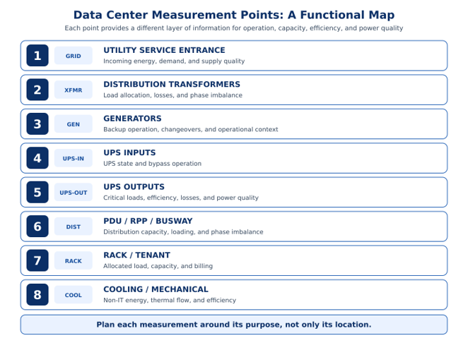
No single measurement point can meet every requirement. Meter location, accuracy, and measurement capability should be derived from the boundary and resolution required for the specific operational, calculation, or commercial purpose.
Non-IT Loads: Not Only How Much Is Consumed, but Where It Belongs
When discussing data center efficiency, it is easy to treat Non-IT loads as the difference between total facility energy and IT equipment energy. This is useful for facility PUE, but for facility management it is only the beginning.
Non-IT loads include cooling and heat-transfer systems, pumps and fans, humidification and dehumidification systems, air conditioning, UPS and transformer losses, distribution losses, lighting, safety and security systems, the BMS, and other infrastructure services.
For overall PUE, it is not necessary to measure every Non-IT component separately, provided that total facility energy and IT equipment energy are measured at the correct boundaries. At the level of a hall, room, PDU, tenant, cage, or rack, however, it is necessary to determine which share of the Non-IT loads belongs to each entity. To obtain a reliable picture at these levels, the relevant Non-IT components should be measured separately wherever possible. Calculation, allocation, or estimation should be used only where direct measurement is not possible.
Measurement Versus Allocation
Some Non-IT systems clearly belong to a specific area. An air-conditioning unit serving one room, a dedicated pump, or an in-row cooling unit serving a group of racks can be measured directly. By contrast, a central cooling system, UPS, or other shared system may serve several areas. Three categories of data should therefore be distinguished:
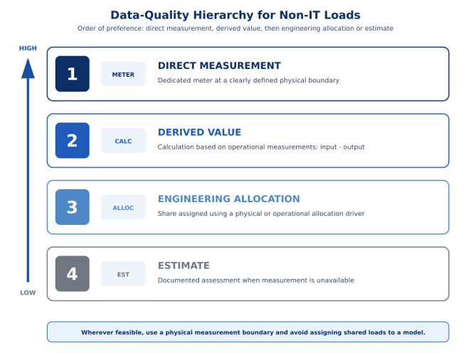
- Measured – a value obtained directly from a meter installed at the appropriate boundary.
- Derived / Calculated – a value derived from several other measurements, such as UPS loss calculated from the difference between input and output energy.
- Allocated / Estimated – a share of a common load assigned to an area or tenant using a formula or engineering model.
Order of Preference: Measure First, Then Calculate
Where a clear physical boundary exists, direct measurement is preferred: dedicated load -> dedicated meter -> direct assignment. As a load is shared by more areas, the approach must shift from physical measurement to an allocation model.
How Should a Shared Cooling System Be Allocated?
When a central cooling system serves several data halls, the electrical meter provides total consumption but does not show how that consumption is divided among the halls. If thermal energy meters are installed on the branches, the measured thermal energy can be used as an allocation driver.
This is an allocation based on measurement, not a direct measurement of the electrical energy consumed by a particular hall. If thermal measurement is unavailable, an alternative model may be used, for example one based on IT energy, but the result is an estimate rather than a direct measurement.
Allocation based on IT energy may be used for comparison or internal cost allocation, but cooling consumption is not necessarily linear with IT load and is also affected by ambient conditions, control settings, and equipment efficiency. Data based on estimation or allocation should therefore be clearly identified.
Electrical Losses Are Also Non-IT Loads
Non-IT loads are not limited to air-conditioning systems and pumps. They also include losses in transformers, UPS systems, PDUs, and conductors, as well as thermal losses in switchboards and the distribution system. Where measurements are available before and after a component, its losses can be calculated from two actual measurements.
For example, if one UPS serves several rooms, its losses may be allocated for internal analysis according to the energy delivered to each branch. Here too, the result is an allocated loss rather than a direct measurement.
Particular Care at the IT Boundary
When Non-IT loads are supplied from the same system at which IT energy is measured, it must not be assumed that all measured energy is IT energy. Meter location alone is not sufficient; the loads downstream of the meter must also be known.
Allocation Becomes More Complex at Rack Level
At rack level, IT energy is relatively easy to measure using a rack PDU. Measuring the rack’s ‘cooling energy’ is more difficult when several cooling units serve a shared space.
Not every Non-IT load needs to be allocated down to rack level. Corridor lighting or a central security system should be included within the appropriate facility boundary, but there is not always a physical basis for assigning such loads to a particular rack. It is better to retain these loads at facility level than to create false precision.
PUE: A Simple Equation, but Not Always a Simple Result
PUE = Total Data Center Energy / IT Equipment Energy
The equation is simple, but the reliability of the result depends on correctly defined measurement boundaries. If part of the cooling or auxiliary systems is excluded from total data center energy, or if Non-IT loads are included in the measurement used for IT equipment energy, the result does not represent the intended measurement boundary.
PUE should therefore be treated as a metric that includes a defined measurement boundary, time period, and measurement method. It can indicate a change in efficiency; correct submetering and allocation help identify the source of that change. At room, tenant, or rack level, it is also necessary to consider whether the value is measured directly or relies in part on calculations and allocations of shared loads.
Power Quality: A Different Layer of Information
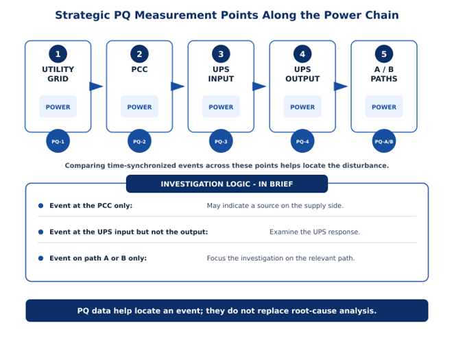
Power quality is not part of the PUE equation, but it is essential to understanding the performance of the electrical system. An energy meter measures energy and power; a power quality measurement system is required to identify voltage dips and swells, interruptions, imbalance, harmonics, and fast events.
The current edition of IEC 61000-4-30 defines methods for measuring and interpreting power quality parameters in AC power systems and distinguishes between Class A and Class S.
This does not mean that Class A measurement is required throughout the facility. The appropriate power quality measurement level should be selected according to the purpose: operational monitoring, compliance with applicable standards, and the actual requirements of the electricity supplier.
Where Should Power Quality Be Measured?
Utility Service Entrances
This is the reference point for the quality of the power supplied by the utility. Measurement at this point helps distinguish an event originating outside the facility from an internal event. Where measurements must support formal comparison and documentation, the selected instrument should meet the Class A requirements of IEC 61000-4-30.
UPS Input and UPS Output
A synchronized comparison of UPS input and output data supports event investigation and helps determine how an event affected the critical load. The purpose is not to assign the cause automatically, but to provide a sequence of data that helps locate the disturbance as part of a root-cause investigation.
A and B Supply Paths
The separation between A and B paths must also be preserved for power quality. An event on one path differs from an event affecting both paths, and combining the data may conceal information needed to investigate the behavior of the redundant system.
Data Quality: A Prerequisite for Reliable Metering and Decision-Making
High-quality measurement equipment alone does not create a reliable system. Data must be time-synchronized, tagged using consistent naming, and linked to the correct topology. Sampling and logging resolution, retention of events and power quality data, and consistent interfaces to the EMS, DCIM, and BMS must all be defined. Otherwise, individual measurements may be accurate while the overall system view remains incomplete or incorrect.
When measurement boundaries, topology, allocation methods, and data quality are defined consistently, an EMS can provide genuine operational value.
Analytics and AI tools can then assist with detecting anomalies, comparing areas, identifying patterns, and investigating root causes. However, even an advanced algorithm cannot compensate for source data that do not correctly represent facility conditions, whether the data are measured or estimated.
Conclusion: Design the Metering Architecture Before Selecting the Meters
Data center metering design begins by defining the measurement objectives, boundaries, and intended uses of the data. The facility type, business model, criticality level, A/B paths, IT and Non-IT boundaries, cooling and water systems, and commercial boundaries must be mapped. These definitions determine the measurement points, required level of power quality measurement, PUE boundaries and calculation method, and the methods used for allocation and estimation.
In a conventional facility, the metering system may be used primarily for energy management and consumption control. In a data center, it is an engineering, operational, and business information layer. Its data influence capacity expansion, investment timing, use of reserves, load transfers between paths, cost allocation, SLA management, maintenance, and evaluation of efficiency projects. The required data, measurement boundary, and resolution must therefore be defined in advance for each decision and operating scenario.