Swiftly locating and fixing this ground-zero of the fault occurrence is key for getting power back up.
BIG SAVINGS WITH DISTANCE TO FAULT CALCULATION
+ Economical solution using a Distributed Digital Fault Recorder
+ Minimizing post-fault downtime by directing maintenance teams to exact fault location
+ Easy installation: zero outage / downtime required for retrofit
Minimize Downtime & Losses
Power outages can cause devastating losses in millions. Quite often the cause of these outages are different fault currents. Minimizing down time and the substantial resulting savings depends a lot on the speed at which the actual fault location is determined. SATEC introduces a fault detection technique, determining exactly that at the utmost accuracy, leading to big savings.
Power Outage and Financial Cost
Large scale power outages cause losses in millions, and even billions, of dollars. For example, the financial damage of a 2003 power outage in Italy, lasting between 3-16 hours, was estimated at more than 1 billion euros (€1,182M*).
Naturally, not all outages are on national scale. However, from large scale to extremely localized, each outage comes with a price-tag of revenue losses for the system operator and loss of productivity and damage to power-dependent systems in the commercial and private sectors.
* https://link.springer.com/article/10.1007/s00450-014-0281-9
Speed is the Keyn
However, once an outage does occur, the primary goal is repairing it and resuming power supply promptly.
A leading cause of power outage is fault current, where a phase-to-phase short circuit or ground fault, causes currents to swell dangerously, tripping protection relays, resulting in power outage. Such events can be caused by the tearing of power lines or a phase-to-phase short-circuit.
The SATEC Solution
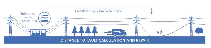
To this end SATEC has developed a fault locating functionality. By allowing network operator to pinpoint the geographic origin of the fault in overhead lines, downtime can be considerably mitigated. Maintenance teams are directed to the site in an extremely accurate manner, saving time and resources.
The PM180 Digital Fault Recorder
This solution is based on SATEC’s PM180 multi- function power quality analyzer. Designed as a modular device, it can house a Digital Fault Recording module. This module features current inputs, recording upto 40 times the rated nominal current, allowing it to capture the full fault current waveform, avoiding saturation. Event recording includes waveform capture and up to 20 pre-fault cycles.
Zero Outage Installation
On the hardware level, the PM180 also stores a unique advantage, simplifying the implementation of the solution. This comes in the form of the SATEC branded HACS current transformers (CTs) which have an option for clip-on/split-core CT models (see fig.5, page 6). This enables live installation of the analyzer/ DFR on to the secondary current of protection CTs’, which are normally installed in substations. Thus, no outage/downtime planning is required, storing more savings.
Impedance Based Calculations
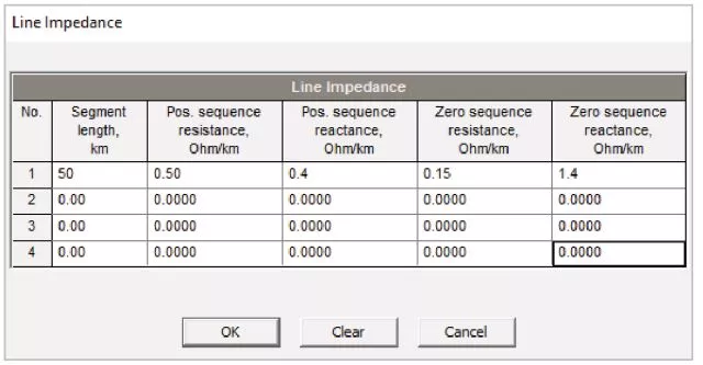
The fault locator uses impedance-based fault location methods. Distance calculations are based on voltage and current waveforms recorded by the device in response to a detected fault event, and line impedance parameters provided by the user (see fig.1, page 2). Impedance calculations use synchronous voltage and current phasors or sequence components, depending on the fault location method and the type of line fault.
Fault Types and Corresponding Calculations
Single-Ended Fault
Single-ended fault location is provided by a single device connected to one end of a power line. Single-ended fault location algorithms use one-point measurements and rely on the fault impedance as it is seen from one end of the line. These algorithms are highly sensitive to powerline characteristics, whose exact values are often unknown, as well as to the impact of the fault effects, caused by mutual coupling and ground fault resistance.
Two-Ended Fault
Two-ended fault distance calculations are based on fault data measured by two fault recorders located on both sides of a power line. The devices exchange measured fault information via the Internet, and both make distance calculations using positive or negative- sequence quantities, enhancing accuracy.
Time Synchronization for Two-Ended Fault Location
The two devices exchange measured voltage and current phasor data accompanied by precise timestamps to guarantee that both are referring to the same event.
For inter-device communications, the devices must be connected to the Ethernet or to a wireless cellular network. UDP port 502 is used for exchange of messages between devices.
Time synchronization of phasors is an important component in accurate distance calculations. Using GPS time synchronization is highly recommended and is mandatory when communicating via a cellular network. In the event that communications are provided via fast Ethernet, guaranteeing that message propagation time along the network is stable, the precise clock synchronization is not required. This is since the devices are able to automatically synchronize their local time with the remote device clock via the network.
Live Alert
The PM180 onboard fault locator provides distance to fault information in real-time. It operates on fault events detected and recorded by the PM180 digital fault recorder immediately as events happen
Offline Distance Analysis
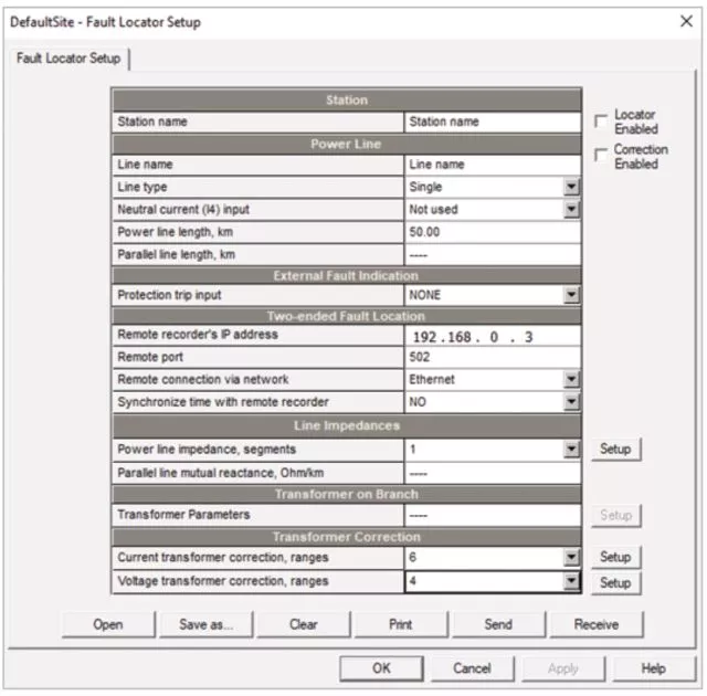
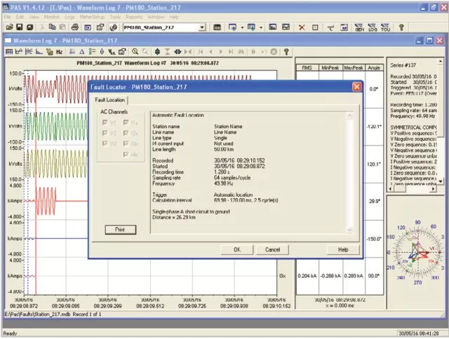
As an alternative approach, SATEC’s supplemental PAS software offers a stand-alone fault locator (see figure 3, page 4 for setup) that can perform fault distance calculations (see figure 4) based on voltage and current waveforms retrieved from PM180 devices. It features the same options as the PM180 onboard fault locator.
User Friendly Interface & Reporting
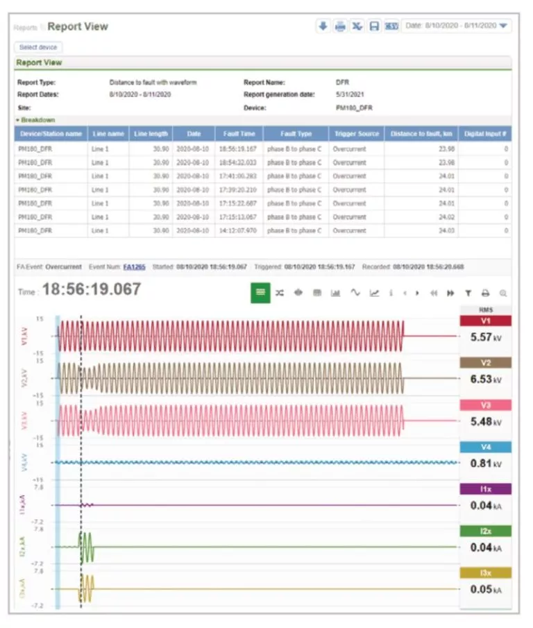
SATEC’s Expertpower software suite supplies a rich interface which can be configured to generate reports (see figure 2, page 3) providing designation of the line, substation, Distance to Fault and fault type (phase to phase, phase to ground etc.).
This way, a full solution is provided, from substation analyzer through diagnostics and actual instructions for field teams.
The Bottom Line: Big Savings in Efficient Repair and Minimized Downtime
Power outages cause losses in millions of dollars. Utilizing SATEC’s PM180 for calculating distance-to-fault enables pinpoint location of the fault site. Swift repair and recovery mitigates outage downtime and minimizes losses.
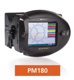
PM180 Power Quality Analyzer

The PM180 is a class A Edition 3 certified (NMI, NL) power quality analyzer. It is designed as a modular device, housing up to 3 additional add-on modules which allow for a variety of functionality and outstanding features, including:
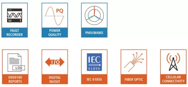
- EN50160 / IEEE 1149 PQ reports
- Phasor Measurement Unit (PMU) functionality, per IEEE 118.1; P-Class and M-Class
- 2, PLC control via up to 48 digital and analog I/O
- Fast Transient Recording (up to 1024 samples/cycle)
- Multi-protocol: IEC 61850; DNP3; IEC 60870-5-101/104
- Multi-interface: serial; fiber-optic ETH; 4G
- 0001Hz reading resolution